Earlier this year (spring 2015) I took a course in Computer Graphics at my university. This was definitely the most interesting course I have taken so far, and I learnt a lot from it. Today I would like to share with you some of the things I learnt during the course.
In my assignments I created a 3D scene using C++ and OpenGL. I implemented the following:
– Wavefront loader
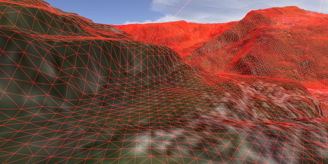
– Heightmap loader (from a raw-file)
– 3D model rendering, with textures and Phong shading
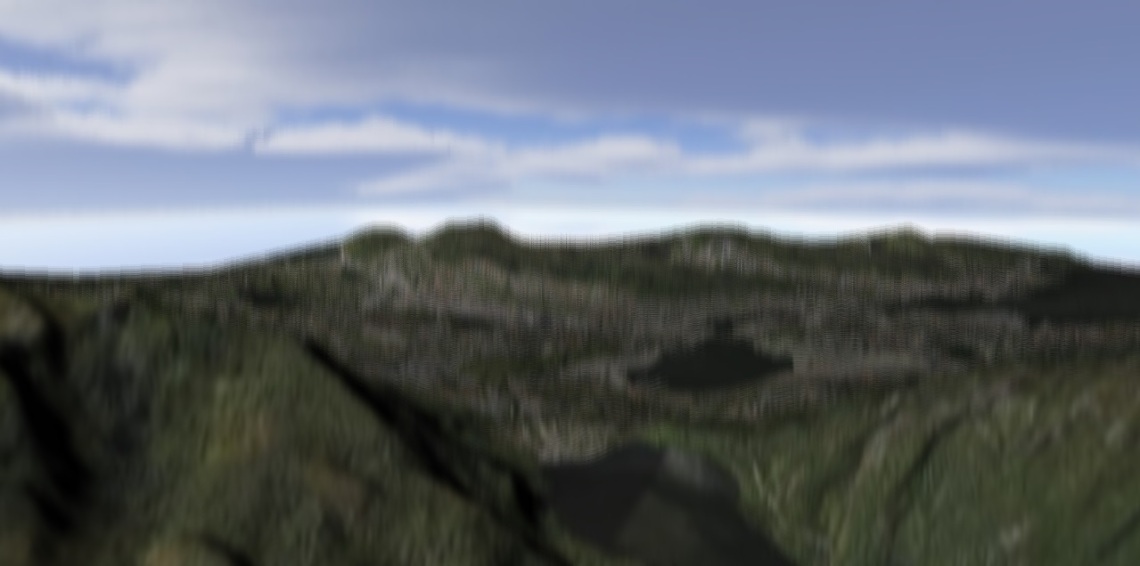
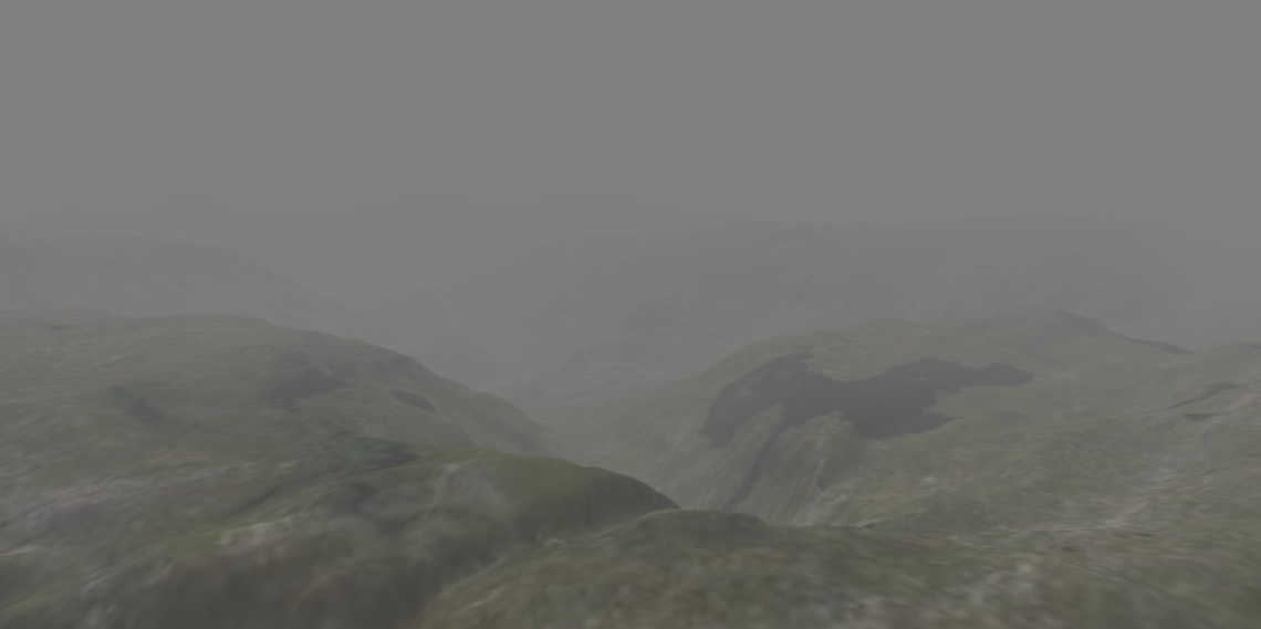
– Different shader effects, such as Gaussian blur, edge detection, normal mapping, relief mapping, fog and more.
– A day-night system, with a sun rotating around the skybox.
– Water with simple waves and “fake” sky-reflection.
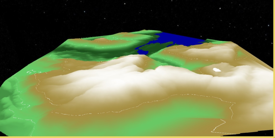
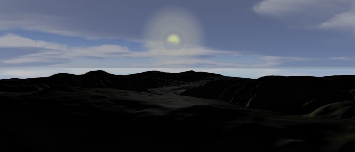
Day-night system
I made a sun that rotates around the skybox. The main directional light moves together with the sun, and when the sun sets the skybox slowly gets filled with stars. This was all implemented in the fragment shader (not very efficient!), so the sun is not a real mesh.
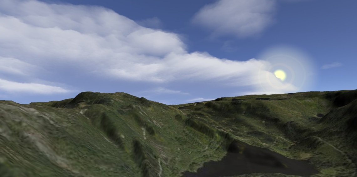
When processing each fragment on the skybox, I calculate the vector from the eye to the point being evaluated and the vector from the point to the sun. Then I take the dot product of these two vectors. If the dot product is close to 1, the two vectors are pointing in the same direction – so the fragment should be coloured yellow. I set a threshold for the dot product (0.95), and used smoothstep to interpolate the colour intensity within this threshold.
Relief mapping
Relief mapping is a simple bump-mapping technique that does not require a bump-map or normal-map.
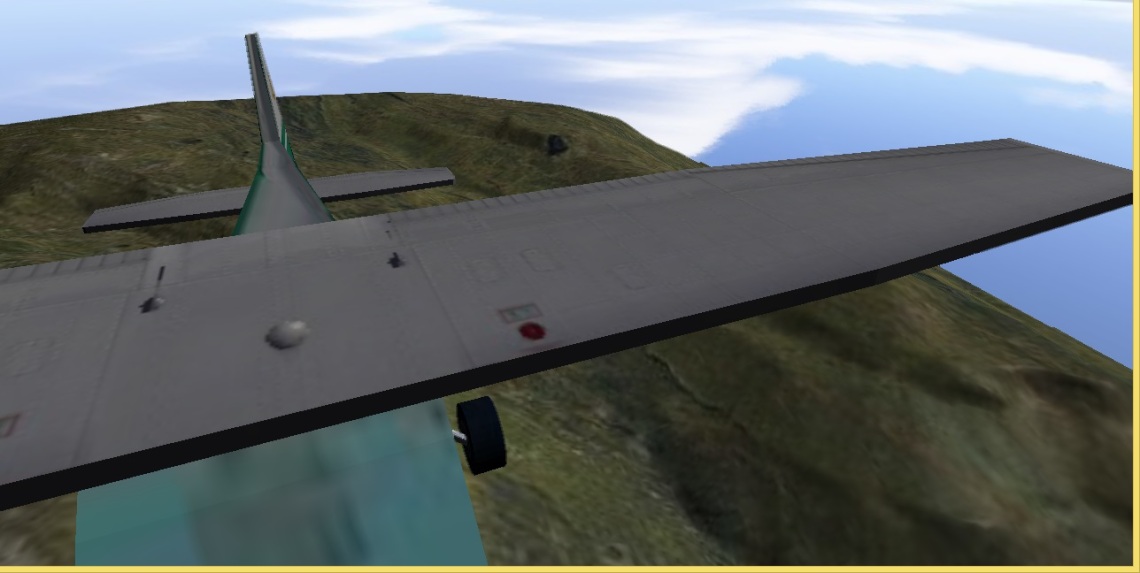
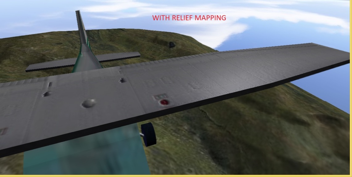
Relief mapping uses information in the main texture, rather than a separate bump map.It is very well described in the book “Computer Graphics with OpenGL” by Pearson, but this is the general idea:
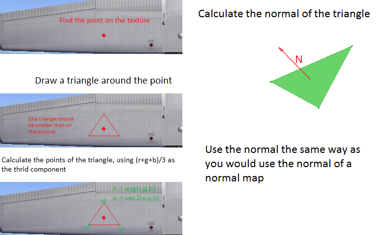
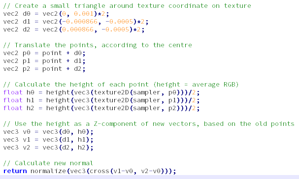
This is all done in the fragment shader. For each fragment you evaluate, pick three nearby texture coordinates around the current texture coordinate being evaluated. This will be our “immaginary” triangle. Since the texture is two-dimentional, we already know the X and Y coordinates of these points. We set the Z-coordinate to be the “height” of the point, which is calculated as the colour intensity of the texture coordinate. Then we calculate the normal of this triangle. We use this normal as we would use the normal of a normal-map (if you want to test this on an unrotated mesh, you can simply use the calculated normal when calculating diffuse and specular lighting).
Water
The water is a low-poly plane. Waves are created in the vertex shader using the sine and cosine of time and position: sin(waveWidth + pos.x + time) * cos(waveWidth + pos.z + time) * waveHeight;
There are of course more realistic alternatives for creating waves.

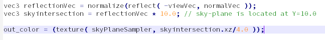
In order to create the “fake” sky reflections, I simply trace the reflection vector of the fragment being evaluated (in the fragment shader) and find the intersection point with my immaginary sky-plane. Finding the intersection point is easy: simply multiply the normalised reflection vector by the Y-position of the sky-plane. Then use the x -and y-position of this vector as the texture coordinate, and look up the colour in the sky-plane sampler. In order to get more “colourful” normal vectors I used a normal-map on the water surface.
Some more screenshots: